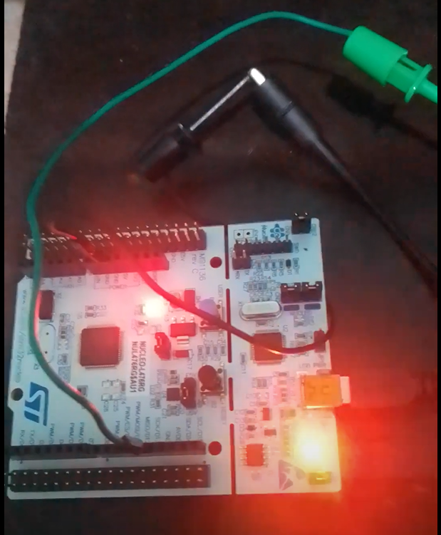


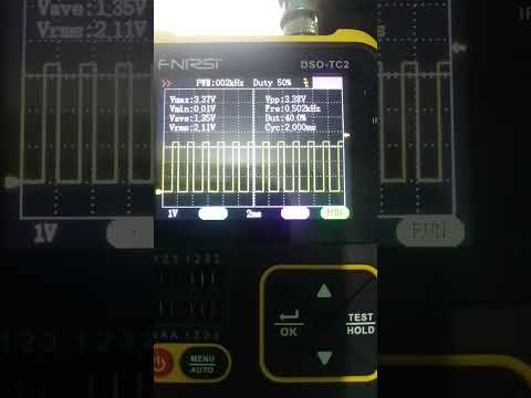
Demonstration of duty cycle control in PWM signal through messages transmitted via CAN BUS.
In the demonstration, the CAN BUS system was used in loopback mode for simplification, since messages were sent and received in CAN BUS using the same MCU (STM32-L476RG).
This way, it was not necessary to assemble the physical network connections between two MCUs.
The transmitted messages contain 4 16-bit integers that correspond to the PWM duty cycle to be supplied to 4 different DC motors.
It was necessary to convert the 16-bit numbers into 2 8-bit numbers each for traffic on this network. (CANBUS requirement)
After the data is transmitted, it is reconstituted to the original 16-bit integers.
After validation, these numbers are directly written to the CCR (Timer Channel Register) registers of one of the MCU timers, and the PWM is generated.
As everything was done to control 4 motors, 4 timer channels were used (indicated by the corresponding CCR registers). – one per engine.
The next step will be to separate the system into two MCUs, one to decide the 4 PWMs and consequently the speed of the motors and send these values via CAN BUS to a second MCU that will receive the messages and generate the PWMs directly controlling the motors via a driver.
The first MCU must run with Azure RTOS (Threadx) and the second must run a bare metal system.
Motor control using CAN BUS messages